Showing posts with label P2MP. Show all posts

Monday, September 19, 2011

Label Switched Multicast - mLDP

 
On any MPLS cloud, current deployment is in a way that Unicast traffic were label switched while Multicast traffic were not.  Current deployment requires Multicast to be enabled on SP core in order to provide Multicast service to SP Customers. In case of MVPN, Multicast traffic from VPN customer will be encapsulated using GRE with destination as multicast address within SP cloud and will be flooded downstream to other PE devices.

Recent enhancement allows providing Multicast service to end customers without enabling Multicast on SP core. This is done by using Multipoint LSP.  Below are the 2 protocols that can be used to build Multipoint LSP:

1.       Multicast LDP (mLDP)
2.       Point to Multipoint Traffic Engineering Tunnel (P2MP TE)

There are 2 types of Multipoint LSPs as below:

1.       Point to Multipoint LSP
2.       Multipoint to Multipoint LSP

Point to Multipoint LSP

Point to Multipoint LSP is a unidirectional LSP with one Ingress LSR and one or more Egress LSR and labeled data replication happening on Branch LSR. P2MP LSP can be established by both mLDP as well P2MP TE. This can be used in application like IPTV video distribution.

Multipoint to Multipoint LSP

This is bidirectional LSP which is currently supported by mLDP only. This can be used in application like Video conference which required bidirectional communication. MP2MP LSP can be used as P-Tunnel to provide Multicast support over BGP/MPLS IP VPN .

In this document, we will discuss about basics of mLDP and the related configuration to enable P2MP and MP2MP LSP using mLDP.

Terminology
Description
P2MP LSP
LSP with one ingress LSR and more than one egress LSR.
MP2MP LSP
LSP that connects a set of nodes in a way that traffic sent by node will be delivered to all other nodes.
Root Node
This plays an important role with mLDP. Any LSR will establish the LSP towards Root node.
Ingress LSR
LSR that sends data packet into an LSP.
Egress LSR
LSR that removes data packet from LSP for further processing.
Transit/Midpoint LSR
LSR that replicates the label packet from upstream to one or more downstream LSRs.
Bud LSR
LSR that have directly connected receivers ( acts as egress LSR) as well have one or more downstream LSR (replicates packet to downstream LSR)
Leaf Node
Any LSR with receivers are termed as Leaf node. It can be either an Egress or Bud LSR.

mLDP overview:
mLDP also known as Multipoint LDP is an extension of LDP protocol that helps establish P2MP and MP2MP LSP in the network. With mLDP, LSP establishment is receiver driven that egress LSR will create LSP whenever there is an interesting receiver.  On receiving interested receiver, mLDP will create the LSP towards Root node. The Root address will be derived either from BGP next hop of the source or through static configuration.

Support for establishing multipoint LSP should be negotiated as part of Session Initialization message. LDP capabilities have been enhanced with new TLV that will be advertised in the LDP Initialization message to negotiate P2MP (0x0508) and MP2MP (0x0509) support capabilities.

As like LDP, mLDP Label Mapping Message carries FEC TLV and Label TLV. FEC elements which will be carried within FEC TLV specify the set of packet/traffic to be mapped to that specific LSP. mLDP uses three different type of FEC element to build MP-LSP as below,

Ø  P2MP FEC Element
Ø  MP2MP Upstream FEC Element
Ø  MP2MP Downstream FEC Element

Below is the FEC Encoding,
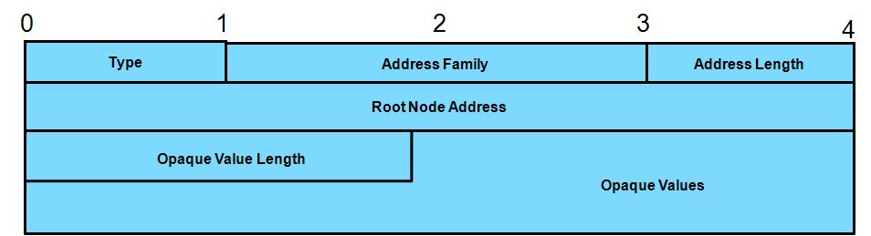
 

Parameter
Description
FEC Type
Type of FEC element. P2MP (0x06); MP2MP Upstream (0x07); MP2MP Downstream (0x08)
Address Family
Root Node Address Type. IPv4 or IPv6
Address Length
Root Node Address Length. IPv4 (32 bits); IPv6 (128 bits)
Root Node Address
Root Node
Opaque Value length
Length of Opaque value in octets
Opaque Values
One or more Opaque values which will be used to identify the MP LSP.

Root Node Address

This field carries address of the Root Node towards which the Multipoint LSP will be established.

Opaque Value


Opaque value plays a key role in differentiating MP LSP in the context of Root Node.  Opaque value is TLV based and the value may vary based on the application for which MP LSP is established. For example, it might be (S,G) for PIM SSM transit while will be MDT default value in case of MVPN.

Below is the Opaque TLV format,


Opaque Value
Description
Type = 00
Manual or Static provisioned MP LSP
Type = 01
Dynamically provided MP LSP for BGP MVPN (Auto discovery)
Type = 02
Statically provisioned MP LSP for MVPN.

P2MP LSP Establishment


1.       Any Leaf node interested in receiving the application stream over P2MP LSP will identify the corresponding Root Node and generate  FEC Element.
2.       The Leaf node will now identify the UPSTREAM router to reach the Root Node (based on RIB entry) and will send Label Mapping for the FEC value.
3.       Any Transit router on receiving P2MP Label Mapping message from DOWNSTREAM router will confirm that the advertising router is not the UPSTREAM for the associated ROOT. Once confirmed, it will check for any existing state entry for the FEC element

a.  If it already has the state entry, advertised label details will be updated in the table for replication.
b.  If it doesn’t have an entry, it will create one and will update the advertised label in table for replication. It now will allocate a local label for the FEC and will advertise to UPSTREAM router towards ROOT.
4.       ROOT node on receiving P2MP label mapping from DOWNSTREAM router will create a state entry if it doesn’t have one and will use the LSP to sent desired traffic.

MP2MP LSP Establishment

 
As we saw earlier, MP2MP LSP is a bidirectional LSP which needs to be signaled both upstream and downstream direction. MP2MP LSP upstream path uses MP2MP UPSTREAM FEC and is ORDERED mode while MP2MP LSP downstream path uses MP2MP DOWNSTREAM FEC.

1.       Any interesting Leaf node will allocate a local label for MP2MP DOWNSTREAM FEC and advertise the same via Label mapping message to upstream LSR.  This LSR will also expect MP2MP UPSTREAM label mapping from upstream LSR for FEC .
2.       Any Transit LSR on receiving label mapping for MP2MP downstream FEC will confirm that it is not received from UPSTREAM LSR for the associated ROOT. Once confirmed, it will check for any existing state entry for the FEC element

a. If it already has the state entry, advertised label details will be updated in the table for replication. It now will check if it has received the UPSTREAM label mapping for the FEC value and if so, will advertise the local upstream label to downstream LSR.
b. If it doesn’t have the state entry, it will create one and will advertise the local downstream label to UPSTREAM LSR towards ROOT. It also now will wait for a UPSTREAM label for the FEC from UPSTREAM LSR before advertising local upstream label to DOWNSTREAM LSR.
3.       ROOT node on receiving MP2MP downstream label mapping from DOWNSTREAM LSR will create a state entry if it doesn’t have one and generate a local upstream label and advertise the same to DOWNSTREAM LSR.
4.       DOWNSTREAM LSR on receiving the upstream label mapping will generate a local upstream label for the FEC and will advertise towards DOWNSTREAM LSR.

Root Node Redundancy

It can be observed that Root Node plays a key role in MP LSP establishment. P2MP LSP and MP2MP downstream LSP will be established towards ROOT while MP2MP upstream LSP will be established from ROOT. So Root node redundancy is a major factor to be addressed as part of network resiliency.

For redundancy, MP LSP will be established to 2 different ROOT node. Any Leaf can receive traffic from any of the ROOT nodes.

In case of P2MP LSP, traffic for a particular FEC should be sent only by one ROOT to avoid packet duplication and inefficient bandwidth utilization.

In case of MP2MP LSP, any leaf node should send the traffic to only one ROOT while can received traffic from any ROOT. This again is to avoid packet duplication and inefficient bandwidth utilization.

Courtesy:

http://tools.ietf.org/html/draft-ietf-mpls-ldp-p2mp-15
http://tools.ietf.org/html/draft-bishnoi-mpls-mldp-opaque-types-01


Sunday, February 13, 2011

Label Switched Multicast - P2MP TE

On any MPLS cloud, current deployment is in a way that Unicast traffic were label switched while Multicast traffic were not label switched. Current deployment requires Multicast to be enabled on SP core in order to provide Multicast service to SP Customers. Multicast traffic from customer will be encapsulated using GRE with destination as multicast address within SP cloud and will be flooded downstream to required PE devices.

Recent enhancement allows providing Multicast service to end customers without enabling Multicast on SP core. This is done by using Multipoint LSP. Below are the 2 protocols that can be used to build Multipoint LSP:


1.       Multicast LDP
2.       Point to Multipoint Traffic Engineering Tunnel (P2MP TE)

There are 2 types of Multipoint LSPs as below:

1.       Point to Multipoint LSP
2.       Multipoint to Multipoint LSP


Point to Multipoint LSP:

Point to Multipoint LSP is an unidirectional LSP which is supported by both mLDP as well P2MP TE. This can be used in application like IPTV video distribution.

Multipoint to Multipoint LSP:

This is bidirectional LSP which is currently supported by mLDP only. This can be used in application like Video conference which required bidirectional communication.

LSM helps us introduce MPLS features like FRR to Multicast traffic as well. It also helps us predefine the path (using MPLS TE) that a particular Multicast stream should take.

In this document, we will discuss about basics of P2MP TE and the related configuration.

P2MP TE tunnel:

P2MP tunnel comprises of LSP which has single ingress and multiple egress points which can be used for services that delivers data from single source to multiple receivers. (Example: Multicast traffic). Incoming MPLS label packets can be replicated to different outgoing interface with different labels.  It consists of multiple sub-LSP which connects the source to multiple destinations.

Below are the few elements which are part of P2MP LSP,


Terminology
Description
Ingress LSR
The head end router where the P2MP LSP is originated. This is responsible for initiating the signaling messages on control plane to setup the Multipoint LSP
Egress LSR/Leaf LSR
One of the tail end routers where the Multipoint LSP will be terminating
Bud LSR
An LSR that is an egress LSR but also have downstream LSRs connected. This LSR will replicate the incoming Multicast packet.
Branch LSR
The LSR which has more than one downstream LSRs connected. This is responsible for replicating the incoming label packet and sent through multiple downstream routers with different labels.

 
RSVP Extensions:

As RSVP is the key protocol to have MPLS TE work, It has been extended with new modified objects which can be used for P2MP TE signaling. 2 New Class types (C-Types) are defined for SESSION object as below,

13  à P2MP_LSP_TUNNEL_IPv4
14  à P2MP_LSP_TUNNEL_IPv6
 
“Destination ID” in SESSION Object is replaced by “P2MP IP”. The combination of P2MP_ID, Tunnel ID and Extended Tunnel ID provides a globally unique identifier for P2MP tunnel.

New Object S2L_SUB-LSP IPv4 has been introduced which will be identified by Class number 50 to define the Tunnel destination (tail end address).

How does RSVP signaling works?
The head end LSR will send RSVP PATH message to the pre defined tail end routers. This PATH message for a P2MP tunnel will have the below objects,

SESSION Object with  unique (P2MP_ID, Tunnel_ID, Extended_Tunnel_ID)
HOP Object with next hop details to reach the tail end.
ERO Object with path details to reach the tail end (with strict/loose sub object information)
LABEL REQUEST object
SESSION ATTRIBUTE with setup, Hold Priority
SENDER TEMPLATE Object with S2L Sub LSP destination address which is the tail end address.

For each destination (Leaf LSR) part of P2MP tunnel, one PATH message will be unicast with “Router Alert” set and with above mentioned objects.

P2MP Configuration Example:

This configuration is under assumption that basic routing and mpls traffic-eng configuration is enabled already. No special configuration is required on any mid routers. Only TE headend and tailend will require special configuration which is as below,

HeadEnd device (R1) Configuration:

1.       Tunnel mode should be configured as “tunnel mode mpls traffic-eng point-to-multipoint”
2.       Tunnel destination will be a list with all leaf node address mentioned.
3.       IP multicast should be enabled with PIM mode as Source Specific Multicast.
4.       Tunnel interface should be enabled with “pim passive”.
5.       IGMP static-group should be configured for each multicast group that will be sent out of P2MP  tunnel interface.
 

hostname R1
!
ip cef   
!
mpls traffic-eng tunnels
!
mpls traffic-eng destination list name P2MP_DESTINATION
ip 10.1.3.3 path-option 1 dynamic
 ip 10.1.4.4 path-option 1 dynamic
 ip 10.1.5.5 path-option 1 dynamic
!
interface Loopback0
 ip address 10.1.1.1 255.255.255.255
!        
interface Tunnel100
 ip unnumbered Loopback0
 tunnel mode mpls traffic-eng point-to-multipoint
 tunnel destination list mpls traffic-eng name P2MP_DESTINATION
 tunnel mpls traffic-eng priority 7 7
 tunnel mpls traffic-eng bandwidth 1000
!
interface Ethernet0/0
 no ip address
!
interface Ethernet0/0.12
 encapsulation dot1Q 12
 ip address 10.1.12.1 255.255.255.0
 mpls traffic-eng tunnels
 ip rsvp bandwidth 5000
!
router ospf 1
 router-id 10.1.1.1
 log-adjacency-changes
 network 10.1.0.0 0.0.255.255 area 0
 mpls traffic-eng router-id Loopback0
 mpls traffic-eng area 0
!
end
  
TailEnd device (R5) Configuration:

1.       IP multicast shold be enabled with PIM mode as Source Specific Multicast.
2.       Static mroute should be configured for each source address of the multicast with next hop as tunnel source address.

hostname R5
!
ip cef
!
!        
ip multicast-routing
ip multicast mpls traffic-eng
!
!
no ipv6 cef
multilink bundle-name authenticated
mpls traffic-eng tunnels
!
interface Loopback0
 ip address 10.1.5.5 255.255.255.255
 ip pim sparse-mode
 ip igmp join-group 232.1.1.1 source 192.168.1.1
!
interface Ethernet0/0
 no ip address
!        
interface Ethernet0/0.5
 encapsulation dot1Q 5
 ip address 10.1.55.5 255.255.255.0
 ip pim sparse-mode
 ip igmp static-group 232.1.1.1 source 192.168.1.1
!
interface Ethernet0/0.35
 encapsulation dot1Q 35
 ip address 10.1.35.5 255.255.255.0
 mpls traffic-eng tunnels
 ip rsvp bandwidth 5000
!
router ospf 1
 router-id 10.1.5.5
 log-adjacency-changes
 network 10.1.0.0 0.0.255.255 area 0
 mpls traffic-eng router-id Loopback0
 mpls traffic-eng area 0
 mpls traffic-eng multicast-intact
!
ip pim ssm default
ip mroute 192.168.1.1 255.255.255.255 10.1.1.1
!
end 

Verification:

Below is the output of multicast ping triggered from CE device connected to Tunnel Headend,

CE#ping 232.1.1.1                  

Type escape sequence to abort.
Sending 1, 100-byte ICMP Echos to 232.1.1.1, timeout is 2 seconds:

Reply to request 0 from 10.1.3.3, 4 ms
Reply to request 0 from 10.1.4.4, 4 ms
Reply to request 0 from 10.1.5.5, 4 ms
CE#

On Headend device, below are the few commands which can be helpful for troubleshooting.

1. "show ip mroute" and "show ip mfib" will show the incoming and outgoing interfaces for each group along with the packet counters. From the below capture, it can be observed that incoming interface for group (232.1.1.1, 192.168.1.1) is E0/0.16 and outgoing interface is Tunnel100.


R1#show ip mfib 232.1.1.1
Entry Flags:    C - Directly Connected, S - Signal, IA - Inherit A flag,
                ET - Data Rate Exceeds Threshold, K - Keepalive
                DDE - Data Driven Event, HW - Hardware Installed
I/O Item Flags: IC - Internal Copy, NP - Not platform switched,
                NS - Negate Signalling, SP - Signal Present,
                A - Accept, F - Forward, RA - MRIB Accept, RF - MRIB Forward
Forwarding Counts: Pkt Count/Pkts per second/Avg Pkt Size/Kbits per second
Other counts:      Total/RPF failed/Other drops
I/O Item Counts:   FS Pkt Count/PS Pkt Count
Default
 (192.168.1.1,232.1.1.1) Flags:
   SW Forwarding: 1560/0/100/0, Other: 15/0/15
   Ethernet0/0.16 Flags: A
   Tunnel100 Flags: F NS
     Pkts: 786/0

R1#


2. "show mpls traffic-eng tunnel tunnel <>" will show the outgoing physical interface and the label used for each Sub-LSP as below,

R1#show mpls traffic-eng tunnels tunnel 100

Tunnel100   (p2mp),  Admin: up, Oper: up
  Name: R1_t100  

  Tunnel100 Destinations Information:

    Destination     State SLSP UpTime 
    10.1.3.3        Up    00:00:44  
    10.1.4.4        Up    01:19:17  
    10.1.5.5        Up    01:19:17  

    Summary: Destinations: 3 [Up: 3, Proceeding: 0, Down: 0 ]
      [destination list name: P2MP_DESTINATION]

  History:
    Tunnel:
      Time since created: 2 hours, 19 minutes
      Time since path change: 1 hours, 19 minutes
      Number of LSP IDs (Tun_Instances) used: 5
    Current LSP: [ID: 5]
      Uptime: 1 hours, 19 minutes
    Prior LSP: [ID: 3]
      Removal Trigger: tunnel shutdown
         
  Tunnel100 LSP Information:
    Configured LSP Parameters:
      Bandwidth: 1000     kbps (Global)  Priority: 7  7   Affinity: 0x0/0xFFFF
      Metric Type: TE (default)

  Session Information
    Source: 10.1.1.1, TunID: 100

    LSPs
      ID: 5 (Current), Path-Set ID: 0xDD000004
        Sub-LSPs: 3, Up: 3, Proceeding: 0, Down: 0

      Total LSPs: 1

P2MP SUB-LSPS:

 LSP: Source: 10.1.1.1, TunID: 100, LSPID: 5
     P2MP ID: 100, Subgroup Originator: 10.1.1.1
     Name: R1_t100
     Bandwidth: 1000, Global Pool

  Sub-LSP to 10.1.4.4, P2MP Subgroup ID: 1, Role: head
    Path-Set ID: 0xDD000004
    OutLabel : Ethernet0/0.12, 17
    Next Hop : 10.1.12.2
    Explicit Route: 10.1.12.2 10.1.23.2 10.1.23.3 10.1.34.3
                    10.1.34.4 10.1.4.4
    Record   Route (Path):  NONE
    Record   Route (Resv):  NONE

  Sub-LSP to 10.1.5.5, P2MP Subgroup ID: 2, Role: head
    Path-Set ID: 0xDD000004
    OutLabel : Ethernet0/0.12, 17
    Next Hop : 10.1.12.2
    Explicit Route: 10.1.12.2 10.1.23.2 10.1.23.3 10.1.35.3
                    10.1.35.5 10.1.5.5
    Record   Route (Path):  NONE
    Record   Route (Resv):  NONE

  Sub-LSP to 10.1.3.3, P2MP Subgroup ID: 3, Role: head
    Path-Set ID: 0xDD000004
    OutLabel : Ethernet0/0.12, 17
    Next Hop : 10.1.12.2
    Explicit Route: 10.1.12.2 10.1.23.2 10.1.23.3 10.1.3.3
    Record   Route (Path):  NONE
    Record   Route (Resv):  NONE
R1#


On midpoint device, below commands can be used for troubleshooting.

1. Use "show mpls forwarding-table label <>" to check the egress label and interface details,
R2#sh mpls forwarding-table labels 17 detail
Local      Outgoing   Prefix           Bytes Label   Outgoing   Next Hop   
Label      Label      or Tunnel Id     Switched      interface             
17         17         10.1.1.1 100 [5] 103578        Et0/0.23   10.1.23.3  
        MAC/Encaps=18/22, MRU=1500, Label Stack{17}
        AABBCC03EB00AABBCC03EA00810000178847 00011000
        No output feature configured
    Broadcast
R2#


On Bud router and Tailend devices, below commands can be used for troubleshooting.

R3#show mpls forwarding-table labels 17 detail
Local      Outgoing   Prefix           Bytes Label   Outgoing   Next Hop   
Label      Label      or Tunnel Id     Switched      interface             
17         17         10.1.1.1 100 [5] 105774        Et0/0.34   10.1.34.4  
        MAC/Encaps=18/22, MRU=1500, Label Stack{17}
        AABBCC03EC00AABBCC03EB00810000228847 00011000
        No output feature configured
    Broadcast
           17         10.1.1.1 100 [5] 105774        Et0/0.35   10.1.35.5  
        MAC/Encaps=18/22, MRU=1500, Label Stack{17}
        AABBCC03ED00AABBCC03EB00810000238847 00011000
        No output feature configured
    Broadcast
           No Label   10.1.1.1 100 [5] 0             aggregate 
        MAC/Encaps=0/0, MRU=0, Label Stack{}, via Ls0
        No output feature configured
    Broadcast
R3#

R3#show ip mroute 232.1.1.1
IP Multicast Routing Table
Flags: D - Dense, S - Sparse, B - Bidir Group, s - SSM Group, C - Connected,
       L - Local, P - Pruned, R - RP-bit set, F - Register flag,
       T - SPT-bit set, J - Join SPT, M - MSDP created entry, E - Extranet,
       X - Proxy Join Timer Running, A - Candidate for MSDP Advertisement,
       U - URD, I - Received Source Specific Host Report,
       Z - Multicast Tunnel, z - MDT-data group sender,
       Y - Joined MDT-data group, y - Sending to MDT-data group,
       V - RD & Vector, v - Vector
Outgoing interface flags: H - Hardware switched, A - Assert winner
 Timers: Uptime/Expires
 Interface state: Interface, Next-Hop or VCD, State/Mode

(192.168.1.1, 232.1.1.1), 00:01:20/00:01:39, flags: sLTI
  Incoming interface: Lspvif0, RPF nbr 10.1.1.1, Mroute
  Outgoing interface list:
    Ethernet0/0.3, Forward/Sparse, 00:01:20/00:01:39

R3#


Points to Remember:


  • P2MP TE can be used only on source driven multicast application. Currently it doesnt support receiver driven applications.
  • Only PIM SSM can be used and other may not be supported.
  • On Tail end devices, a new virtual interface LSPVIF will be created and used as incoming interface for LSM traffic.
  • On Headend router, tunnel mode must be point-to-multipoint traffic-eng. (Use "tunnel mode mpls traffic-eng point-to-multipoint")
  • On Headend router, tunnel destination is a list of sub LSP address.